|
Sliding Gates
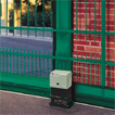
844 MC Gearmotor
DEAL FOR COMMERCIAL OR INDUSTRIAL GATES
The 844 gearmotor was designed to move the heaviest commercial or industrial gates in the simplest, most convenient way.
TOTAL SAFETY
The special twin-disk anti-crushing clutch, in oil bath, enables thrust adjustment from 0 to 110 daN. As the gearmotor is non reversing, no electric locks need be installed and, in the event of power failure, the key-operated release device makes it possible to open and close the gate manually. LONG LIFE Constant, complete oil-bath lubrication of mechanical components plus assembly in a high resistance pressure-cast aluminium body ensure a very long life.
RELIABLE, SAFE ELECTRONICS
All commands come from a control board with microprocessor, on the leading-edge in terms of safety and reliability. Leaf stopping space can be electronically programmed.
EASY AND INEXPENSIVE
The electronic equipment housed inside the gearmotor facilitates and speeds up installation, at lower cost.
Automated systems for sliding gates - for sliding gates with max weight of 1.800 kg:
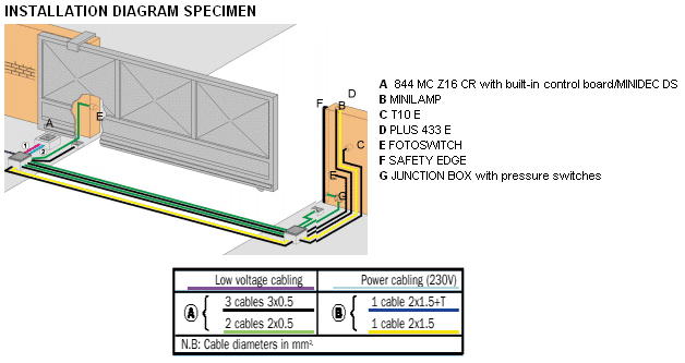
- 844 MC Z16 CR for rack applications
- 844 MC CR for rack applications (without pinion)
- 844 MC CAT for chain applications
- 844 MC RF for chain applications with idle transmission
| Model |
Max weight (kg) |
Use frequency (%) |
| 844 MC Z16 CR |
1.800 |
30 |
| 844 MC CR |
1.800 |
30 |
| 844 MC CAT (*) |
1.800 |
30 |
| 844 MC RF (*) |
1.800 |
30 |
| Technical specifications of 844 MC | Z16 CR | MC CR | MC CAT | MC RF |
| Power supply |
230 V~ (+6% -10%) 50 (60) Hz |
| Absorbed power |
650W |
| Absorbed current |
3,5 A |
| Traction and thrust force |
0÷110 daN (Z16) |
| Motor rotation speed |
1.400 rpm |
| Reduction ratio |
1:30 |
| Operating ambient temperature |
-20°C +55°C |
| Weight with oil |
14,5 kg |
| Protection class |
IP 44 |
| Type of oil |
FAAC OIL XD 220 |
| Gate speed |
9,5 m/min (Z16) |
| Thermal protection on motor winding |
130°C |
| Electric motor |
Single-phase, bi-directional |
| Limit-switch |
Inductive |
| Clutch |
Twin-disk in oil-bath |
Specifications of 844 MPS electronic equipment (Built into Model 844 MC Z16 CR)
| Power supply |
230 V~ (+6% -10%) 50 (60) Hz |
| Motor maximum load |
650W |
| Accessorieses output |
24 Vdc 500 mA max |
| Operating ambient temperature |
-20°C +55°C |
| Three protection fuses |
0,25 A trasformer 5 A motor - 1,6 A Accessorieses |
- SMT Technology
- Programmable functions
- Four function logics A1 - E1 - S1 - S2
- Pause times
- Operation of indicator-light
- Pre-flashing
- Braking control trimmer
- Input and limit-switch signalling LEDs
- Indicator-light output
Specifications of 844 BC electronic equipment
| Power supply |
230 V~ (+6% -10%) 50 (60) Hz |
| Motor maximum load |
650W |
| Operating ambient temperature |
-20°C +55°C |
| Two protection fuses |
0,25 A transformer -5 A motor - 1,6 A Accessorieses |
- Programmable functions
- Four “dead-man” function logics B/C/BC/CB
- Indicator-light output
- Power supply and limit-switch LEDs
844 MC Z16 CR SPECIFICATIONS
Non-reversing screw gearmotor
- Gate maximum weight 1,800 Kg
- Gate speed 9.5 m/min
- Use frequency max. 30%
- Max thrust 110 daN
- Electric motor power supply 230 V (+6% -10%) - 50 (60) Hz
- Electric motor power 650 W
- Thermal protection at 130°C built into motor winding
- Operating ambient temperature -20°C +55°C
- Protection class IP 44
- Lever operated release device with coded key
- Single-phase, bi-directional motor (1,400 rpm)
- Pinion gear Z 16/module 4
- Inductive limit-switch
- Lower and upper half-body in pressure cast aluminium with cataphoresis treatment
- Twin-disk clutch in oil-bath
- Anti-crushing safety to UNI 8612 standards
- Opening/closing force adjustable by hexagonal key
- Galvanised foundation plate with side and height adjustment (optional)
- Dimensions (L x W x H) 280 x191 x 385 mm
- Built-in electronic card
- ABS electronic card enclosure with triangular key
844 MPS electronic card
Electronic card with limit-switch inputs for controlling sliding gate gearmotors
- Motor max load of 650W
- 24 Vdc - 500 mA max. output for Accessories
- Microprocessor control
- 3 protection fuses (motor/Accessorieses - transformer)
- Connector for card receiver/decoding cards
- Separate high and low voltage terminal boards
- Inputs status signalling LEDs
- Programming Dip Switches
- Braking control trimmer
- Automatic (A1-S1-S2) and semi-automatic (E1) function logics
- Two logics for safety devices (Dip Switches)
- Pause times in selection range of 5 s to 180 s (Dip Switches)
- Selectable 5 s pre-flashing (Dip Switch)
- Inputs: closing safety devices, stop push-button, total opening push-button, and limit-switch
- Outputs: power supply for Accessorieses, motor, flashing lamp and indicator-light
|